Upcoming maintenance
Dear Customers and Partners.
This website will be undergoing scheduled maintenance on June 14, 2023. Please be aware there may be disruption to the developer portal website and associated services during the scheduled maintenance period.
This upgrade is essential to ensure the continued performance, reliability, and security of Developer World.
We apologize for any inconvenience.
Slow refresh rate streaming the camera preview to a display
-
Issue Description
I experience a slow refresh rate when I am streaming the camera preview to my display.
It takes 420ms to draw a 120x160 area for lvgl and 740ms for Adafruit GFX.
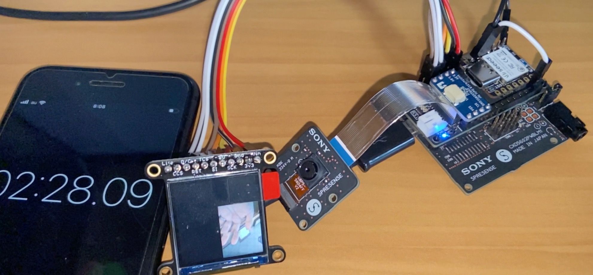
I measured using the slow motion camera and placed a timer next to the screen. I read the timer values and subtracted them. It looks like this
I am not sure what the limiting factor is as I am not so experienced in using displays.
My research so far.
- There are multiple SPIs on the Spresense board. Each has a different maximum speed. Hence asking for expert advice.
- The one I can use on the LTE Extension board is the slowest. The LTE modem seems to occupy the faster SPI4 and uses DMA
- Available SPIs
- Main board SPI5 13Mbps
- Extension SPI4 48.75Mbps (with level shifters which are in use on the extension board around 20MHz
- LTE Extension SPI3 6.5Mbps
- Level shifters which I need when using SPI5 seem to slow down the speed.
- The demos by the Spresense team seem to use another controler which is ILI9340. There is an excellent resource that says it can be driven directly with 1.8V (VCC on 3V)
- Adding buffers seem to improve the speed. (But he is using SPI4)
- A Better Web Camera Powered by Sony - Hackster.io
- My LCD has them already build in.
- I tried Adafruit GFX, but it was slower than my setup.
- The camCB is faster than the display drawing. So I think the limiting factor is the display rendering.
What would be the recommendation to do next?
- Switch to another controller? ILI9340? Which controlers would be fast? (A small display would be nice for the project.)
- Need to switch to 8bit parallel?
- Try to modify the BSP for example enabling DMA? (Sounds time consuming)
- Is it possible
- Try to use the ST7789 borad with SPI5 with and without level shifters (as there are only outgoing signals)?
- Exchange or tweak TFT_eSPI library to optimize for Spresense SPI
- Any ideas?
This is the environment I use
-
Hardware
- LTE extension board (Introduction)
- ST7789 based TFT LCD Display Adafruit 1.3 240x240 Wide Angle TFT LCD Display with MicroSD ST7789 : ID 4313 : $16.95 : Adafruit Industries, Unique & fun DIY electronics and kits
-
Software
- Spresense Reference Board version 2.5.1 (Arduino)
- TFT_eSPI by Bodmer Version 2.4.61
- lvgl by kisvegabor, embeddedt, pete-pjb Version 8.2.0
- Adafruit GFX Library 1.11.1
-
Sketches and Library Modifications
This is my User_Setup.h of TFT_eSPI
#define USER_SETUP_INFO "User_Setup"

#define ST7789_DRIVER

#define TFT_WIDTH  240
#define TFT_HEIGHT 240

#define TFT_MISO      -1
#define TFT_MOSI      (PIN_SPI3_MOSI)
#define TFT_SCLK      (PIN_SPI3_SCK)
#define TFT_CS        (PIN_SPI3_CS0_X)
#define TFT_RST       5
#define TFT_DC        9
// compile error: missing binary operator before token "("
//#define TFT_RST       (PIN_D05)
//#define TFT_DC        (PIN_D09)

// the TFT_eSPI/Processors/TFT_eSPI_Generic.c makes issues so modify line 12 to
// '  SPIClass& spi = SPI3;'
#define TFT_SPI_PORT 3

// #define SPI_FREQUENCY  6500000 440ms
// #define SPI_FREQUENCY  20000000 460ms
#define SPI_FREQUENCY  6500000
// to avoid linker error missing function ltoa
#define ltoa itoa
Modify Arduino/libraries/TFT_eSPI/Processors/TFT_eSPI_Generic.c due to compile issues
// line 11
  SPIClass& spi = SPI3;
Remove this from Arduino/libraries/TFT_eSPI/User_Setup_Select.h as it clashes with Spresense defines
// These are the pins for ESP8266 boards
//      Name   GPIO    NodeMCU      Function
#define PIN_D0  16  // GPIO16       WAKE
#define PIN_D1   5  // GPIO5        User purpose
#define PIN_D2   4  // GPIO4        User purpose
#define PIN_D3   0  // GPIO0        Low on boot means enter FLASH mode
#define PIN_D4   2  // GPIO2        TXD1 (must be high on boot to go to UART0 FLASH mode)
#define PIN_D5  14  // GPIO14       HSCLK
#define PIN_D6  12  // GPIO12       HMISO
#define PIN_D7  13  // GPIO13       HMOSI  RXD2
#define PIN_D8  15  // GPIO15       HCS    TXD0 (must be low on boot to enter UART0 FLASH mode)
#define PIN_D9   3  //              RXD0
#define PIN_D10  1  //              TXD0

#define PIN_MOSI 8  // SD1          FLASH and overlap mode
#define PIN_MISO 7  // SD0
#define PIN_SCLK 6  // CLK
#define PIN_HWCS 0  // D3

#define PIN_D11  9  // SD2
#define PIN_D12 10  // SD4
This are the modifications in my lvgl_conf.h (as described in xn--Arduino LVGL documentation-on5q)
// modified line 15
#if 1 /*Set it to "1" to enable content*/
// modified line 88
#define LV_TICK_CUSTOM 1
This is my minimal sketch sample
// Comment out to switch from lvgl to Adafruit GFX #define USE_LVGL #if USE_LVGL #include <TFT_eSPI.h> #include <lvgl.h> #else #include <Adafruit_GFX.h> #include <Adafruit_ST7789.h> #include <SPI.h> #endif #include <Camera.h> #if USE_LVGL TFT_eSPI tft = TFT_eSPI(); /* TFT instance */ static const uint32_t screenWidth = 240; static const uint32_t screenHeight = 240; static const uint32_t bufHeight = 10; #define TFT_CS PIN_SPI3_CS0_X #define TFT_RST PIN_D05 // Or set to -1 and connect to Arduino RESET pin #define TFT_DC PIN_D09 lv_disp_draw_buf_t draw_buf; lv_color_t buf[screenWidth * bufHeight]; lv_obj_t *lvglCamImage; lv_img_dsc_t img_bg; /* Display flushing */ void my_disp_flush(lv_disp_drv_t *disp, const lv_area_t *area, lv_color_t *color_p) { uint32_t w = (area->x2 - area->x1 + 1); uint32_t h = (area->y2 - area->y1 + 1); uint64_t start = millis(); tft.startWrite(); tft.setAddrWindow(area->x1, area->y1, w, h); tft.pushColors((uint16_t *)&color_p->full, w * h, true); tft.endWrite(); uint64_t end = millis(); lv_disp_flush_ready(disp); } void lcd_show_camera_image(uint8_t *image_buffer, int width, int height) { img_bg.header.always_zero = 0; img_bg.header.w = width; img_bg.header.h = height; img_bg.data_size = width * height * LV_COLOR_SIZE / 8; img_bg.header.cf = LV_IMG_CF_TRUE_COLOR; img_bg.data = (uint8_t *)image_buffer; lv_img_set_src(lvglCamImage, &img_bg); } void setup_tft() { lv_init(); tft.begin(); /* TFT init */ tft.setRotation(0); /* Landscape orientation, flipped */ lv_disp_draw_buf_init(&draw_buf, buf, NULL, screenWidth * bufHeight); /*Initialize the display*/ static lv_disp_drv_t disp_drv; lv_disp_drv_init(&disp_drv); /*Change the following line to your display resolution*/ disp_drv.hor_res = screenWidth; disp_drv.ver_res = screenHeight; disp_drv.flush_cb = my_disp_flush; disp_drv.draw_buf = &draw_buf; lv_disp_drv_register(&disp_drv); lv_obj_set_style_bg_color(lv_scr_act(), lv_color_black(), LV_STATE_DEFAULT); lvglCamImage = lv_img_create(lv_scr_act()); lv_obj_align(lvglCamImage, LV_ALIGN_CENTER, 0, 0); } #else #define TFT_CS PIN_SPI3_CS0_X #define TFT_RST PIN_D05 #define TFT_DC PIN_D09 Adafruit_ST7789 tft = Adafruit_ST7789(&SPI3, TFT_CS, TFT_DC, TFT_RST); void setup_tft(void) { tft.init(240, 240); tft.setSPISpeed(6500000); tft.fillScreen(ST77XX_BLACK); } void lcd_show_camera_image(uint8_t* image_buffer, int width, int height) { tft.drawRGBBitmap(0, 0, (uint16_t*) image_buffer, width, height); } #endif void CamCB(CamImage img) { if (img.isAvailable()) { img.convertPixFormat(CAM_IMAGE_PIX_FMT_RGB565); lcd_show_camera_image(img.getImgBuff(), img.getWidth(), img.getHeight()); } } void setup_camera() { theCamera.begin(1, CAM_VIDEO_FPS_5, CAM_IMGSIZE_QQVGA_V, CAM_IMGSIZE_QQVGA_H, CAM_IMAGE_PIX_FMT_RGB565, 7); theCamera.startStreaming(true, CamCB); theCamera.setAutoWhiteBalanceMode(CAM_WHITE_BALANCE_DAYLIGHT); theCamera.setStillPictureImageFormat(CAM_IMGSIZE_QUADVGA_H, CAM_IMGSIZE_QUADVGA_V, CAM_IMAGE_PIX_FMT_JPG); } void setup() { Serial.begin(115200); while (!Serial) {} setup_tft(); setup_camera(); } void loop() { #if USE_LVGL usleep(5); lv_timer_handler(); #endif } - There are multiple SPIs on the Spresense board. Each has a different maximum speed. Hence asking for expert advice.
-
Update:
- It has to be
#define USE_LVGL 1. The 1 was missing. - I attached the TFT to the SPI5 directly.
- Adafruit GFX now takes only about 190ms
- Lvgl only takes about 120ms
- I had some trouble with the eTFT_SPI though.
- It was not working at all using the 1.8V pins. (or I messed some configuration up while trying it. See last item below)
- It was working using the 1.8V SPI5 SCK and MOSI and for all other pins I used the 3V ones on the LTE extension board (as described above)
- I also noticed
- that TFT_MOSI and TFT_SCLK was not in use for eTFT_SPI as it uses SPI5.
- As eTFT_SPI sends the pin numbers through Arduino's pin_convert() I am confused why the PIN_SPI3_CS0_X assignment to TFT_CS worked. Maybe because SPI3 uses hardware cs and SPI5 not? (see comment in SPI.cpp begin() "Control CS by hardware" if (spi_port == SPIDEV_PORT_3)) For SPI5 it had to be the correct Arduino number to work (32)
I would like to know if the speed of different SPIs is hardware or software design dependent. Is it possible to increase the speed by makding modifications to the BSP?
- It has to be
-
Hey, @jens6151-0-1-1
I believe the speed of the SPI is mostly hardware dependent. It depends on the maximum clock rate of the SPI. Have you tried increasing it?
There is one hackster project that uses LCD display and codes in arduino. https://www.hackster.io/karl-sony/spresense-audio-scope-e0c3d3
This project uses the TFT library for arduino, but uses the ST7735 display, but they modified this library in order to get make the display faster.
This commit on git shows the differences in the library:
https://github.com/TE-KarlKomierowski/TFT/commit/ffbab7269e7ef7470f10a6f63fd077cfa46db180#diff-27aa76e18c68c455fb3f55d132033cefe6326ac2b171cebe21ad3f6f9e827d59
In line 381 you see that they changed the SPI settings.It's a little hard to know whats wrong with the TFT_eSPI usage because it wasn't made for Spresense.
I hope this other example can shine some light on your problem. Let me know if it was helpful at all.
-
Hi @CamilaSouza
Thanks for pointing me to another sample. Yes it was the SPI speed that needed to be increased. However just increasing it did not work as SPI3 was already at max. Sure TFT_eSPI is a 3rd party library, so I digged a little deeper into it.
I was able to highly increase (sorry for not having a concrete number, but it was faster than the 5Hz refresh rate I set for the camera stream without any tearing for a larger area 240x160) the speed to refresh the display. These were the steps
Summary
- (1) Use the SPI5 on the Spresense board (2) with DMA enabled and (3) push all pixels at once.
More detail
- Recompile the arduino SDK with one change in configuration which is to activate CONFIG_LCD_ON_MAIN_BOARD.
- This enables DMA on SPI5. You only need to activate it. Then the SPI transfer call from Arduino SDK automatically uses DMA.
- Add the following code to your initialization of the display (yes the include is hacky as this is not exported to the Arduino SDK)
#include "/Users/jens/work/mcu_prj/prj/spresense/references/spresense-sdk/spresense/nuttx/arch/arm/src/cxd56xx/cxd56_spi.h" #include <arch/board/board.h> static void initDMA() { #if defined(CONFIG_CXD56_DMAC) DMA_HANDLE hdl; dma_config_t conf; hdl = cxd56_dmachannel(DISPLAY_DMA_TXCH, DISPLAY_DMA_TX_MAXSIZE); if (hdl) { conf.channel_cfg = DISPLAY_DMA_TXCH_CFG; conf.dest_width = CXD56_DMAC_WIDTH8; conf.src_width = CXD56_DMAC_WIDTH8; cxd56_spi_dmaconfig(DISPLAY_SPI, CXD56_SPI_DMAC_CHTYPE_TX, hdl, &conf); } hdl = cxd56_dmachannel(DISPLAY_DMA_RXCH, DISPLAY_DMA_RX_MAXSIZE); if (hdl) { conf.channel_cfg = DISPLAY_DMA_RXCH_CFG; conf.dest_width = CXD56_DMAC_WIDTH8; conf.src_width = CXD56_DMAC_WIDTH8; cxd56_spi_dmaconfig(DISPLAY_SPI, CXD56_SPI_DMAC_CHTYPE_RX, hdl, &conf); } #endif }- Now you can set SPI speed higher because you can use SPI5 without level shifters.
- It worked on the ST7789 too without level shifters. I only use MOSI and CLK on the main board. Other connections are to LTE extension board. So a 1.8V and 3.3V mix. (I assume connecting MISO which is unused would destroy the board as the display runs on 3.3V ...)
- Max speed is 48.75Mbps according to the documentation. I set it to 30 Mhz, otherwise I get artifcats on the screen. If you have a good connection, maybe 40 Mhz will work (see define in board.h ILI9340_SPI_MAXFREQUENCY 40000000).
- By using lvgl, I actually only draw pixels in a region directly, thus only the TFT_eSPI function pushPixels() is used. That function transferred 16 bit at a time via SPI. Modifying this function to transfer all data at once greatly increased speed again. (that means I modified TFT_eSPI so much that it is used only for initialization)
void TFT_eSPI::pushPixels(const void* data_in, uint32_t len){ spi.transfer(data_in, len); }- You need to take care of display endianess if you transfer all at once, so swap the colors before transferring them.
void swapColors(uint16_t *colors, uint32_t len) { uint16_t *data = (uint16_t *)colors; while (len--) { *data = __builtin_bswap16(*data); data++; } } -
@jens6151-0-1-1
Wow! You did an amazing job!Thank you for sharing your solution. It will help out many users in the future.
-
@jens6151-0-1-1 I am using an Adafruit ILI9341 Arduino shield with the extension board. The FPS is very slow and drawRGBBitmap (Adafruit GFX) is taking 725ms to render a single frame. I think I do not need to recompile the SDK since the CONFIG_LCD_ON_EXTENSION_BOARD is already enabled. How can I make it faster as you've mentioned 190ms for the Adafruit GFX library? I have copied your initDMA() code but seems not working. Do I need to change it for the extension board?
-
Hi @yokonav
I assume you draw the camera image or draw large image data.Can you make sure that you transfer the pixel data at once using the spi function with *data and lenght parameter? I think that requires modification of Adafruit GFX library.
spi.transfer(data_in, len);Can you make sure that the SPI frequency is set to a high frequency for the Adafruit GFX.
What is your screen size? I was using only a small screen. That might make a big difference.
Do you use the Adafruit GFX library only to draw the camera or for more?
I do not think you need to recompile just countercheck that your config.h points to SPI4.
-
Hi @jens6151-0-1-1,
Yes, I am trying to render the camera frames (320x240) only to the LCD. I tried to change the drawRGBBitmap to use SPI.transfer but it does not display anything so I may be missing something. By the way how does the DMA work? Shouldn't DMA copy the camera frame buffer to LCD automatically?
-
@yokonav
Have a look at spresense-sdk/spresense/nuttx/arch/arm/src/cxd56xx/cxd56_spi.c
Do a text search on "dmaenable". After initialization, spi_exchange is mapped to spi_dmaexchange and does the work.Unfortunately I do not have the extension board (only LTE) and no ILI9341 (only ST8879) displays, so I cannot try things out.
My suggestion would be to either try out TFT_eSPI with the changes above and check if you see any difference or use Adafruit GFX but bypass it for drawing the camera image.
This could be snippets for bypassing it based on what is TFT_eSPI is doing. I did an extract of minimal required parts from TFT_eSPI in my case.
Keep in mind that I modified this for your case. I believe it works for ili9481 too but I cannot guarantee anything. I also did not compile this.
// please download the file #include https://github.com/Bodmer/TFT_eSPI/blob/master/TFT_Drivers/ILI9481_Defines.h #define TFT_CS xxxx #define TFT_DC xxxx // try modifications when it works #define SPI_FREQUENCY 30000000 #define TFT_SPI_MODE SPI_MODE3 static void begin_tft_write() { SPI4.beginTransaction(SPISettings(SPI_FREQUENCY, MSBFIRST, TFT_SPI_MODE)); digitalWrite(TFT_CS, LOW); } static void end_tft_write() { digitalWrite(TFT_CS, HIGH); SPI4.endTransaction(); } void swapColors(uint16_t *colors, uint32_t len) { uint16_t *data = (uint16_t *)colors; while (len--) { *data = __builtin_bswap16(*data); data++; } } void pushPixels(const void* data_in, size_t len) { SPI4.transfer(data_in, len); } void setAddrWindow(int32_t x0, int32_t y0, int32_t w, int32_t h) { begin_tft_write(); int32_t x1 = x0 + w - 1; int32_t y1 = y0 + h - 1; x0 += colstart; x1 += colstart; y0 += rowstart; y1 += rowstart; digitalWrite(TFT_DC, LOW); SPI4.transfer(TFT_CASET); digitalWrite(TFT_DC, HIGH); SPI4.transfer16(x0); SPI4.transfer16(x1); digitalWrite(TFT_DC, LOW); SPI4.transfer(TFT_PASET); digitalWrite(TFT_DC, HIGH); SPI4.transfer16(y0); SPI4.transfer16(y1); digitalWrite(TFT_DC, LOW); SPI4.transfer(TFT_RAMWR); digitalWrite(TFT_DC, HIGH); end_tft_write(); } void my_disp_flush(CameraImage img) { uint32_t x = 0; uint32_t y = 0; uint32_t w = img.getWidth(); uint32_t h = img.getHeight(); setAddrWindow(x,y, w, h); begin_tft_write(); swapColors((uint16_t *) img.getImgBuff() , img.getWidth() * img.getHeight()); pushPixels(img.getImgBuff(), img.getImgBuffSize()); end_tft_write(); } -
Thanks, @jens6151-0-1-1!
The code you provided works with minimal change. I do not need to include any config since the TFT_eSPI library has a default driver set for ILI9341. It takes 95ms to render a single frame which is almost 8 times faster! Increasing SPI frequency does not change the fps so I guess 30MHz is the saturation point. I think this is due to logic-level translation between the main and extension board, reducing the data transfer rate. Now if I call the initDMA() in setup, the performance is the same. What could be the reason?
PS: Instead of calling initDMA one time at initialization, I am calling it before the rendering frame and now the rendering time for a single frame is 80ms!!! The swapColors is taking 8ms which is an extra burden.
Thank you again for your help!
-
Changing the mode, it reduces to 70ms per frame!!!
#define TFT_SPI_MODE SPI_MODE1 -
@yokonav
Thanks for the hints for SPI_MODE1 and the time consumption of the swap bytesIt looks like Spresense uses the 2D Graphics hardware acceleration for the conversion, so we cannot hook in there.
However I found this. Seems like our issue is not new.
https://stackoverflow.com/questions/41675438/fastest-way-to-swap-alternate-bytes-on-arm-cortex-m4-using-gccSo changing the swap to this halfs the time.
inline uint32_t Rev16(uint32_t a) {
  asm("rev16 %1,%0" : "=r"(a) : "r"(a));
  return a;
}

void swapColors(uint16_t *colors, uint32_t len) {
  len = len / 2;
  uint32_t *data = (uint32_t *)colors;
  for (uint32_t i = 0; i < len; i++) {
    data[i] = Rev16(data[i]);
  }
}
Though it looks like hacky. It seems the loop consumes some time and it is possible to squees a little more performance out with this. Don't ask why. It was empirical try & error.
void swapColors(uint16_t *colors, uint32_t len) { // works only if length is dividable!! Is the case here. len = len / 64; uint32_t *data = (uint32_t *)colors; while ( len-- ) { *(data) = Rev16(*(data)); *(data + 1) = Rev16(*(data + 1)); *(data + 2) = Rev16(*(data + 2)); *(data + 3) = Rev16(*(data + 3)); *(data + 4) = Rev16(*(data + 4)); *(data + 5) = Rev16(*(data + 5)); *(data + 6) = Rev16(*(data + 6)); *(data + 7) = Rev16(*(data + 7)); *(data + 8) = Rev16(*(data + 8)); *(data + 9) = Rev16(*(data + 9)); *(data + 10) = Rev16(*(data + 10)); *(data + 11) = Rev16(*(data + 11)); *(data + 12) = Rev16(*(data + 12)); *(data + 13) = Rev16(*(data + 13)); *(data + 14) = Rev16(*(data + 14)); *(data + 15) = Rev16(*(data + 15)); *(data + 16) = Rev16(*(data + 16)); *(data + 17) = Rev16(*(data + 17)); *(data + 18) = Rev16(*(data + 18)); *(data + 19) = Rev16(*(data + 19)); *(data + 20) = Rev16(*(data + 20)); *(data + 21) = Rev16(*(data + 21)); *(data + 22) = Rev16(*(data + 22)); *(data + 23) = Rev16(*(data + 23)); *(data + 24) = Rev16(*(data + 24)); *(data + 25) = Rev16(*(data + 25)); *(data + 26) = Rev16(*(data + 26)); *(data + 27) = Rev16(*(data + 27)); *(data + 28) = Rev16(*(data + 28)); *(data + 29) = Rev16(*(data + 29)); *(data + 30) = Rev16(*(data + 30)); *(data + 31) = Rev16(*(data + 31)); data += 32; } } -
@jens6151-0-1-1
There seems to be an issue with the loop that some data is skipped. Need to check that maybe later. -
@jens6151-0-1-1 said in Slow refresh rate streaming the camera preview to a display:
There seems to be an issue with the loop that some data is skipped. Need to check that maybe later.
Thanks for your time! By the way I was checking the function call imageproc_convert_yuv2rgb which seems using the hardware to convert YUV to RGB. They are setting some register value ROT_RGB_ALIGNMENT which looks like the order but I am not sure. If we can directly output BGR instead of RGB, would it be same as colors swapping?
-
@yokonav
I do not think that ROT_RGB_ALIGNMENT is related to the byte order we need.
I assume it is for the RGB 888 or BGR 888 format. (1 byte per color)
We have 5-6-5 bit for the color channels. That makes up 2 bytes or 16 bit.
Byte order means that 1st byte (bit 0-7) and 2nd byte (8-15) is exchanged for a 2 byte number. -
@jens6151-0-1-1
I think it is RGB565. See the code snippet below from the Arduino SDK.CamErr CamImage::convertPixFormat(CAM_IMAGE_PIX_FMT to_fmt) { CAM_IMAGE_PIX_FMT from_fmt = getPixFormat(); int width = getWidth(); int height = getHeight(); uint8_t *buff = getImgBuff(); if (buff == NULL) { return CAM_ERR_NOT_PERMITTED; } switch (from_fmt) { case CAM_IMAGE_PIX_FMT_YUV422: switch (to_fmt) { case CAM_IMAGE_PIX_FMT_RGB565: imageproc_convert_yuv2rgb(buff, width, height);The code converts YUV422 (16bit) input to RGB565 (16bit) output and overwrites the input buffer with the output by the HW.
-
@yokonav
I tried to change this line to use 1 or 2. But I do not see any difference. I hope I did not make any mistake. I recompiled, replaced the sdk, cleaned by deleting all intemerdiate files ...putreg32(0, ROT_RGB_ALIGNMENT);Without any documentation difficult to say. Even the https://www.sony-semicon.co.jp/products/common/pdf/CXD5602_user_manual.pdf did not mention the registers.
@CamilaSouza Is it possible that the 2D Graphics hardware acceleration returns "display byte order"? -
@yokonav
Just had the idea to look up the display handling inside the Spresense SDK.This looks promising but might not be supported.
spresense-sdk/spresense/nuttx/include/nuttx/spi/spi.h#ifdef CONFIG_SPI_HWFEATURES /* If there are multiple SPI drivers, some may not support hardware * feature selection. */ ... * Bit 4: HWFEAT_LSBFIRST * Data transferred LSB first (default is MSB first) */ ...Need to continue to investigate on the sdk samples later.
-
@jens6151-0-1-1
This should be working.
putreg32(1, ROT_RGB_ALIGNMENT);@jens6151-0-1-1
There is an entry for the register in the https://github.com/sonydevworld/spresense/blob/master/sdk/tools/SVD/rot.xml file.
<register> <name>RGB_ALIGNMENT</name> <description>RGB format selector</description> <addressOffset>0x38</addressOffset> <access>read-write</access> <resetValue>0x00000000</resetValue> <resetMask>0x00000001</resetMask> <fields> <field> <name>FORMAT</name> <description>RGB Format</description> <bitRange>[0:0]</bitRange> <enumeratedValues> <enumeratedValue><name>RGB</name><value>0</value></enumeratedValue> <enumeratedValue><name>BGR</name><value>1</value></enumeratedValue> </enumeratedValues> </field> </fields> </register> -
@yokonav
It seems like imageproc_convert_yuv2rgb is not called. It is only called if you convert formats, but not called if you set the desired format in the first place.
I tried forcing a call by converting formats. Unfortunately it was slow. I assume the asm optimized conversion is the best trade off for now.